-
Products
- ++ HV Connection Systems ++
- FLRY Cable
- ABB Harnessflex
- Aptiv (Delphi) Connectors
- FCI Connectors (Delphi)
- VW Connectors
- Kostal
- Bosch Compact Series
- Deutsch - DT Series
- Deutsch - DTM-Series
- Deutsch - DTP Series
- Deutsch - HDP20 + HD30-Series
- Amphenol - AT Series
- Amphenol - ATM Series
- TE AMP Superseal 1.5 Series (Tyco)
- TE MQS-Series (Micro Quadlok System Series)
- TE AMP MCP 2.8 Series (multi contact point)
- Trailer Connectors
- Oil Pressure Switches
- Crimping tools
- Yazaki
- Coroplast Tape
- Miscellaneous

16/12/2024
US-Parts ... lange gesucht, hier - noch zu in Deutschland - endlich gefunden, und das zu absolut realistischen Preisen

05/12/2024
Schnell, unkomplitziert und günstig - Gern wieder! :-)

05/12/2024
Excellent company with good stock and great customer service. The only address that you need for automotive connectors!

04/12/2024
Great communication and very helpful in finding the right part for a great price

02/12/2024
Muy buen servicio.

26/11/2024
Meine Email Anfrage wurde innerhalb von Sekunden bearbeitet und alle Fragen beantwortet. Die Bestellung wurde sofort abgewickelt. Vorbildliche Kundenbetreuung. Vielen Dank.

23/11/2024
Vielen Dank, schnelle Lieferung, alles wie beschrieben und zum fairen Preis. Konnte nun den Marderschaden an meinem 28 Jahre altem T4 entlich professionell reparieren.

21/11/2024
TOP Ware, sehr schnelle Lieferung und sehr gute Kommunikation. Ich war auch schon persönlich bei DayTrade und habe Stecker gesucht, man war sehr freundlich und hilfsbereit, vielen Dank!!!

08/11/2024
Die bestellten Ersatzteile sind sehr schnell geliefert worden ohne. Bitte weiter so.

16/10/2024
I have been buying all sorts of connector parts for many years now. Quick shipping, reasonable prices they got it all :).

15/10/2024
Sehr schnelle Bearbeitung und Versand

15/10/2024
Good prices and a lot of car related connectors! Highly recommended!

09/10/2024
perfekt, schnelle Bearbeitung, im Shop alles sehr übersichtlich und einfach.

07/10/2024
Freitag Mittag bestellt, Samstag Mittag da, besser geht´s nicht, echt großes Kino, werde Euch weiterempfehlen, ich bin wirklich begeistert. Vielen Dank

05/10/2024
Gutes Sortiment an Steckverbindundungen, sowie Rep-Sätze für Kabelbäume. Ausführliche Maße und Ausführunge sind beschrieben. Für unseren Oldtimer sind alle Kabel und Stecker vorhanden. Die richtigen Stecker und Kabel wurden schnell gefunden. Hilfreich ist, wenn die OEM-Nummer bekannt ist.

26/09/2024
Objednávka přišla rychle a v pořádku.

24/09/2024
Alles bestens, gerne wieder, hohe Qualität und sehr schnelle Lieferung

19/09/2024
Really good shop with nice price. Very quick to deliver my order and response to my question. Excellent service.

18/09/2024
Schneller Versand, gute Kommunikation, gerne wieder.

18/09/2024
Super das es so was noch gibt, wo man die Stecker einzeln bekommt!! Top 👍

16/09/2024
for a first order with you, very positive experience. Very good reception, compliant order, rapid administrative follow-up. Serious company. Address to keep.

09/09/2024
Always nice to work with!!!

06/09/2024
Super toller Onlineshop. Danke für die günstigen Preise und den schnellen Versand :-)

02/09/2024
Schnelle Rückmeldung und Versand.

27/08/2024
Schnelle Lieferung, super Qualität

26/08/2024
Es gibt sie noch, die "Serviceperlen". Ich restauriere gerade den Kabelbaum von einem alten Ferrari und deytrade wurde mir in einem Forum wärmstens empfohlen. Zu recht, wie sich herausstellen sollte. Montag morgen kurz mit dem Inhaber telefoniert, der mir mehrere Empfehlungen ausgesprochen hat, dann gegen mittag online bestellt und Dienstag um 11 Uhr war das Paket schon da. Ernsthaft: besser geht es nicht. Vielen Dank!!!

20/08/2024
Always great service and good stocks of connectors. +++++++

19/08/2024
Sehr schnelle Lieferung Top Kommunikation gerne wieder

03/08/2024
Perfekt. Sehr schneller Versand.

31/07/2024
Bei DeyTrade funktioniert es ganz einfach. Gesucht >>>> Gefunden! Super!

31/07/2024
Excellent Service Very fast reaction and respect of promised delivery date. Thank you very much

26/07/2024
Super Abwicklung und schneller Versand. Top, hier bestelle ich wieder

24/07/2024
Vielen herzlichen Dank an DeyTrade Connecting GmbH&Co.KG! Ich kann nur empfehlen!Wenn eine KFZ Stecker nicht mehr gibt dort wird man definitiv fündig! Und dort passt einfach alles! Super schnelle Lieferung und super Preis !👍

22/07/2024
This company literally saved me. A wiring harness in my vehicle broke and i looked everywhere for a “pigtail” To avoid having to buy the entire wiring kit. They not only had the pigtail harness, they had it for a great price (I think the expedited shipping cost more than the part). I was back up and running within two days. Service was great and communication from Sebastian and Anna. Thanks!

19/07/2024
Super schneller Versand alles richtig - gerne wieder

08/07/2024
Gute Beratung, schnelle Lieferung

21/06/2024
Quick, perfect supplier.

20/06/2024
Ok, great contact

11/06/2024
I'm customer from many years. It's a very good shop for connectors and terminals. Fast shopping and good Price.

10/06/2024
Für Kabelfreaks geeignet!

07/06/2024
Fast answer, very good communication.

05/06/2024
Klasse Händler. Ich bestelle hier nicht zum ersten Mal. Es hat immer bestens geklappt, es wurde auch immer zügig bearbeitet und versendet. Vorher per Email gestellte Fragen wenn mir mal etwas unklar war wurden immer schnell und kompetent beantwortet. Also ich kann Herrn Deyter und seinen Shop absolut empfehlen. Top Shop.

03/06/2024
Sehr zuverlässig und fair. Zu empfehlen.

30/05/2024
Extrem schnell geliefert. Ware ordentlich verpackt. Sehr zu empfehlen. Vielen Dank!

29/05/2024
Endlich eine Abdeckung für die ODB2 Buchse zum kleinen Preis.

29/05/2024
Alles in ordnung.

24/05/2024
Top Elektronikladen, große Auswahl und großes Sortiment. Schnelle Bestellungsbearbeitung und super Übersichtlicher Online-Shop.

24/05/2024
Sehr zuvorkommende und kompetente Mitarbeiter. Netter Kontakt, sehr zu empfehlen.

21/05/2024
Alles super! Schnelle unkomplizierte Bestellung und schnelle Lieferung! So macht Einkaufen Spaß!

17/05/2024
Société très sérieuse et personnel à l'écoute. Le top

16/05/2024
Excellent services. Great quality connectors. Fast shipping.

14/05/2024
Complete catalogue and a superb service!!

07/05/2024
Super schnelle Bearbeitung und Versand! Sehr freundlicher Service immer wieder gerne

06/05/2024
Super nett und schnelle Bearbeitung und Lieferung

03/05/2024
Superb service from the start 👍 Great choice of items, clearly identified, simple to order and very quick to respond to any questions. Dey Trade will certainly be my first choice in the future. Keep up the excellent work

29/04/2024
Customer of ours needed these parts for an application of theirs and they couldn't use the pigtails that we were finding. DeyTrade had all the needed parts in stock and at an affordable price and was able to get my order out the same day.

24/04/2024
Absolut super der Shop. Hat mir viel Ärger und Geld gespart und schnell die passenden Kabel geliefert.

24/04/2024
Arbeite beruflich mit Deytrade zusammen. Eine sehr kompetente Firma mit einem breiten Sortiment. Faire Preise und schnelle Lieferung.

23/04/2024
Items I needed were in stock and shipped very quickly. I would happily order from DeyTrade again!

16/04/2024
Sehr guter Service und super schnelle Reaktionszeiten

15/04/2024
Kompetente Beratung telefonisch, guter Preis und Ware ok.

12/04/2024
Good communication, prompt delivery

05/04/2024
5-Sterne -Plus- Shop Absolut zuverlässiger Shop. Beste persönliche Beratung. So konnte ich z.B. (bei einem früheren Problem) den richtigen Pin dadurch finden, dass ich dem freundlichen Herrn am Telefon ein Bild von einem Stecker schicken konnte. Der empfohlene Pin war absolut der Richtige! Auch diesmal: nach kurzer telefonischer Beratung, bei der ich übrigens immer das Gefühl hatte, dass man sich über den Anruf freut, die richtigen Pin´s und Gehäuse bestellt. Super-schnelle Lieferung. Da macht einkaufen wirklich Spaß. Schade ist nur, dass ich nicht häufiger den Shop benötige. Jederzeit, und ich meine wirklich jederzeit, gern wieder. Hoffentlich bleiben Sie mir noch lange erhalten. Gruß TDA G. Ellrich

05/04/2024
Spedizione celerissima e personale molto serio e competente. Consigliato

25/03/2024
Quick delivery

22/03/2024
Alles super!

20/03/2024
Schnelle Abwicklung! Gerne wieder!

29/02/2024
We found this company thru website and made an order of connectors. Their responses to our email inquiry were always prompt, and eventually the package was delivered very smoothly. We are very much satisfied with their service. Thank you.

29/02/2024
All' perfect

23/02/2024
I have dealt with Dey Trade Connecting on numerous occasions, excellent service and communication every time. I recommend this company to everyone. Fast delivery and excellent products.*****

21/02/2024
Netter Kontakt und gute Beratung !!

19/02/2024
Super Verkäufer. Riesige Auswahl und netter Support!

16/02/2024
Sehr zuverlässiger Lieferant. Sehr umfangreiches Portfolio. Bestelle hier schon seit Jahren. Nur zu empfehlen.

15/02/2024
alles super! immer wieder!!

14/02/2024
J'apprécie grandement travailler avec DEYTRADE depuis déjà de nombreuses années ils sont rapides et très professionnelles .

14/02/2024
Super firma. Bardzo dobrze się z nią współpracuje.

13/02/2024
Alles Top.Habe schon öfter bei Deytrade bestellt.

12/02/2024
Top Unternehmen, immer freundlich und schnelle Lieferung.

12/02/2024
Kann ich nur weiterempfehlen. In allen Kategorien einwandfrei.

10/02/2024
Super fast services

08/02/2024
Rasche Abwicklung

07/02/2024
Very quick to ship my items. They are awesome to stock connectors for audi/vw. Very easy to order from the US.

02/02/2024
Excelent

31/01/2024
Everything fast and very good. Thank you so much.

24/01/2024
Super Firma 👍Schnell geliefert Super Kundenservice.Wenn ich gewusst hätte das so eine Firma existiert,werde ich vor einem Jahr nicht die ganze Kabelbaum für meine Auto kaufen müssen für 150€ 🫣 und 99% davon weggeschmissen nur wegen winzigen Stecker.TipTop Firma

24/01/2024
It was a pleasure to buy from; perfect communication, fast shipping. Thanks indeed.

22/01/2024
The place where find everything Automotive connectors!

17/01/2024
Spedizione velocissima. Davvero professionali.

12/01/2024
Alle möglichen Stecker, auch vorkonfektioniert, zum guten Preis vorhanden

03/01/2024
Gut sortiertes Warensortiment. finde auch Stecker für meinen Alten Ami.

27/12/2023
Sehr schnelle und freundliche Reaktion; Turbo Versand. Sehr empfehlenswert, jederzeit gerne wieder. Danke.

18/12/2023
Kompetente und Unkomplizierte Bestellung sowie schnelle Auftragbearbeitung. Sehr gutes Sortiment. Kann ich nur empfehlen!

18/12/2023
Ich bin froh auf dieses Unternehmen gestoßen zu sein. Das Sortiment ist wirklich umfangreich. Ich habe alles zu vernünftigen Preisen gefunden, wovon ich zunächst nicht gedachte hätte, es überhaupt in Deutschland zu bekommen. Nach nicht mal 48h hatte kamen die Artikel bereits an. Die Kommunikation war super und auch bei Rückfragen ist man hier sehr hilfsbereit. Für die Zukunft werde ich mit Sicherheit hierauf zurückgreifen.

12/12/2023
Top, sehr hilfsbereit

09/12/2023
Sehr schnelle Lieferung und tolle Unterstützung bei technischen Fragen! Schön, dass es so etwas heutzutage noch gibt!

08/12/2023
Honest seller. He helped me with the purchase.

05/12/2023
Accurate fast service!

30/11/2023
Super Ware, sehr netter Kundenservice und promte Lieferung

16/11/2023
Schon seit einigen Jahren bestelle ich hier. Das Geschäft zeichnet sich durch hohe Kundenfreundlichkeit, schnellen Versand und ein breites Produktsortiment aus - auch Sonderbeschaffungen waren kein Problem und wurden gleichermaßen stets sehr schnell, freundlich und zuvorkommend erledigt. Ein weiterer Pluspunkt dieses Geschäfts sind die verbindlichen Beratungen per E-Mail. Bestellungen mit der Versandart "Warensendung" haben mich in der Regel in weniger als 48h nach Absenden der Bestellung erreicht.

09/11/2023
First time purchase, fast delivery from the store

07/11/2023
Parfait. Réactif et produits en stock

06/11/2023
Top Internetseite, super Auswahl und schnelle Lieferung!

05/11/2023
Can only be recommended...very fast shipping.

21/10/2023
Übersichtliche Homepage, schnelle Rückmeldungen, rasche Versendung, top!

19/10/2023
Top Beratung, sehr hilfsbereit.

17/10/2023
Super flott und freundlich. Große Auswahl, guter Preis. Gerne wieder.

16/10/2023
Alles super geklappt schnelle Lieferung

11/10/2023
Jedesmal sehr zufrieden. Nette und kompetente Beratung. Dank des großen Sortiments bekommt man alles was man benötigt. Der Ablauf funktioniert immer reibungslos und der Versand ist schnell. Mein Favorit wenn es um Automotive Stecker geht.

02/10/2023
Huge selection of products, correct service, I recommend it to others.

02/10/2023
Super kompetent in der Beratung und ist telefonisch erreichbar

22/09/2023
Ware ist Top und passt. Ratzefatz geliefert, schneller gehts nicht. Vorbildlicher Service.

13/09/2023
Super freundlich, sehr lösungsorientiert, flexibel und gut erreichbar. Egal ob mal ein Teil schlecht verfügbar ist oder eine Bestellung kurzfristig erweitert oder geändert werden soll. Beschriftung und Verpackung der Ware ist vorbildlich.

22/08/2023
Top Beratung per Telefon, jede Frage wurde optimal beantwortet. Bestellung wurde zügig geliefert. Gerne wieder.

22/08/2023
Ausführliches Sortiment und sehr gute Preise. Sehr schnelle Bearbeitung der Aufträge.

10/08/2023
Schnelle und zuverlässige Warenlieferung. TOP-Leistung gut Qualität, genau wie beschrieben.

09/08/2023
Highly recommended. Ordered parts online and received on time per order.

08/08/2023
Alles bestens!

08/08/2023
special parts available, very fast, kind and precise support

08/08/2023
Bestellung wurde sehr schnell geliefert. Alles super!

28/07/2023
Bis jetzt nur sehr gute Erfahrungen gesammelt. Qualität und Versand top.👍🏼

27/07/2023
best place to purchase european connectors
25/07/2023
The only place where to buy so many different connectors and related accessories + a really nice wiki and knowledge area to clarify everything. I recommend to anyone who needs original / OEM quality parts

21/07/2023
Ich bestelle seit mittlerweile 4 Jahren sehr regelmäßig bei DeyTrade größere Mengen an Schüttgut für Fahrzeugkabelbäume. Die (Staffel-)Preise sind konkurrenzlos, ebenso die Abwicklungsgeschwindigkeit. Schön wäre es, wenn auch Kabeltüllen für das JPT-System ins Angebot aufgenommen werden würden.

21/07/2023
Tolle Seite. Sehr freundlich.

19/07/2023
Fast shipping and delivery!

13/07/2023
Sehr freundlicher Kontakt. Super schnelle und sehr kompetente Beantwortung meiner Fragen. Die Firma verwies auf das korrekte und von mir gesuchte Produkt. Online bestellt und am selben Tag verschickt. TOP +++

13/07/2023
Hab schon ab und zu bei DeyTrade bestellt. Es war fast immer alles da und wurde schnell geliefert. Hatte nie Probleme. 👍🏻 Sehr empfehlenswert! .

12/07/2023
Schnelle Lieferung, gute Ware, gute Kommunikation, Bestellfehler von mir sehr schnell korrigiert. TOP !

04/07/2023
Good service, order was confirmed and shipped in a single day. I would recommend.

26/06/2023
Sehr freundlich, absolut zuverlässig, jederzeit gerne wieder

06/06/2023
Top Auswahl. Super Preise. Schneller Versand. Sehr gute Menüführung auf der Website, man findet gleich über den jeweiligen Stecker welche Pins dazu passen etc. Habe schon sehr oft dort gekauft, immer wieder gerne 😊

30/05/2023
Bonne réactivité, site internet bien conçu, tarifs compétitifs. A recommander

25/05/2023
Great communication..I got all the info I needed right away. regarding package delivery. Vielen Dank ERIK Slovenia

20/05/2023
Bestellt und direkt nach halbe Stunde wurden die Teile versendet also das nenne ich mal Kundenservice vielen Dank

19/05/2023
Top. Schnelle Bearbeitung und Lieferung. Auf Rechnung bestellt und drei Wochen Zeit zum bezahlen. Ich bin so begeistert, das ich am Tag der Zustellung schon die Rechnung schon begleiche. 👍🏻👍🏻👍🏻👍🏻👍🏻

16/05/2023
Really quick shipping across the world to get a connector for my car!

15/05/2023
Gute Ware, schneller Versand, bestelle oft dort.

02/05/2023
Schnelle Bearbeitung!

19/04/2023
Top Service am Telefon. Sehr zu empfehlen

13/04/2023
Hier funktioniert alles super.

31/03/2023
Sehr professioneller Internet-Shop, total unkomplizierte Auftragsabwicklung und sehr schnelle Lieferung! Auf Rückfragen bzw. Anmerkungen wird schnell reagiert, zudem ist der Kontakt mit Herrn Deyter (Geschäftsführer) äußerst freundlich! Werde bei Bedarf erneut dort bestellen!

22/03/2023
Sehr schnelle Bearbeitung. Brauchte Pins für einen Stecker die von niemanden nach Österreich geliefert wurden und wenn dann mind. 100 Stück. Konnte einfach die Anzahl bestellen die ich brauchte ich bin begeistert!

17/03/2023
Ein Service, wie man ihn sich überall wünscht. Reaktionszeiten mit Überschallgeschwindigkeit und funktionierende Problemlösungen wie aus der Pistole. 6 von 5 Sternen! ★★★★★★

14/03/2023
Good prices, cheap shipping, fast response and shipping. Highly recommend!

14/03/2023
Enquiry made on day 1 and details and cost provided same day and parts shipped. Could not be better.

13/03/2023
Super.

13/03/2023
Sehr schnelle Bearbeitung. Versand schnell. Schneller Kontakt

10/03/2023
reibungsloser Kauf, Faire Preise. Lieferung innerhalb 22 Stunden!! Was will man mehr?

09/03/2023
Sehr guter Online-Shop mit umfangreichem Sortiment und ultraschnellen Lieferungen. Sehr empfehlenswert!

08/03/2023
Great customer service. Quick reply. Very easy to checkout

08/03/2023
Perfect shop if you need to find some connectors or terminals for your own restorations of vehicles or motorcycles, or to made some preparations. A cordial treatment and they didn't hesitate to help me in the search for specific terminals.

07/03/2023
schnelle Abwicklung und Rückmeldung, Versand... Einfacher geht es nicht, alles TOP

07/03/2023
Great product ( I ordered an extraction tool), great prices and super communication. What a great experience - thank you!

01/03/2023
Hatte sehr netten telefonischen Kontakt und eine sehr kompetente Beratung. Vielen Dank. Ich bin begeistert

28/02/2023
Sensationeller Verkäufer. Einzelner Stecker in Rekodzeit erhalten. Ich bin sehr zufrieden. Kann ich nur jedem weiterempfehlen. Besten Dank…

25/02/2023
Hallo, ich bin von dem Aufbau des Online Shops schwer begeistert! Wenn die Ware und der Versand genau so abgestimmt sind, dann kann ich nur sagen perfekt! Super durchdacht! Vielen Dank

22/02/2023
Sehr schnelle Lieferung

17/02/2023
Online Website ist einfach aufgebaut, man findet sofort das wonach man sucht - super schneller Versand!

08/02/2023
Schneller Versand,super Kommunikation, gerne wieder

07/02/2023
Nette und kompetente Beratung. Super große Artikelauswahl . Schneller Versand.

06/02/2023
Very fast shipping. Lots of connectors in stock. Great staff attitude!

02/02/2023
Für den Poststreik konnte DeyTrade nichts. Die Stecker sind sehr preiswert und das Ausdrückwerkzeuge hält bestimmt bei mir ewig. Es war auch nicht das erste mal, daß ich hier bestellt habe - und nicht das letzte mal.

02/02/2023
Schnelle und immer korrekte Lieferungen. Danke & weiter so!

01/02/2023
Fijn bedrijf met een goed assortiment kwaliteit producten, correcte levering en zeer goede service.

27/01/2023
Top Artikel. Hilft immer wieder

15/01/2023
Sehr kompetente und ausführliche telefonische Beratung, trotzdem ich nur zwei Stecker benötigte, zu denen ich keine genauen Angaben hatte.

14/01/2023
Einziger Laden wo ich diesen einen Stecker so günstig gefunden habe genau so wie ich ihn brauche

06/01/2023
Das Paket ist schneller da als DHL die Sendungsnummer überhaupt anzeigt😄 Alles super, immer wieder gerne! Riesen Auswahl und auch Kleinmengen möglich.

04/01/2023
Schnelle kompetente Abwicklung

03/01/2023
Ich habe DeyTrade vor kurzem erst gefunden. Da ich regelmäßig Automobil-Kabelbäume restauriere aber auch neu anfertige ist diese Firma perfekt für mich. Denn die Preise sind sehr gut und auch die Bestellungsabwicklung findet sehr schnell und Problemlos statt. Zum Beispiel habe ich früher die Connectoren direkt bei BMW bestellt und dort hat ein Kontakt der bei DeyTrade 0,10€ kostet auch mal gut 2€ pro Stück gekostet. Von dem her kann ich diese Firma nur wärmsten empfehlen.

02/01/2023
Superschnelle Lieferung... Qualität der Ware erstklassig. Immer wieder gerne.

29/12/2022
Große Auswahl, alle Stecker separat in einzelnen Tüten gut beschriftet verpackt, sehr schnelle Lieferung und der Preis war auch i. O.

28/12/2022
Klasse Auswahl, top Originalware (z.B. Tyco Kontakte), perfekt in einzelne Tütchen verpackt, sehr faire Versandkosten. Bestelle immer wieder gerne dort!

27/12/2022
Schnelle Antwort, netter Kontakt. Gerne wieder!

21/12/2022
Excellent communication, fair prices and fast shipping. What more could you ask for?

14/12/2022
Für jeden Zweck eine Steckverbindung. Eine überwältigende Vielfalt an OEM-nahen Verbindern. Sehr gute Kommunikation und schneller Versand.

12/12/2022
Sehr grosses Sortiment am verschiedenen PKW Steckern. Viele Artikel ab Lager lieferbar. Bestellung wurde schnell verarbeitet und versandt. Verpackung und Beschriftung der einzelnen Steckerpins war ebenfalls sehr gut gemacht.

09/12/2022
Very fast and very well stocked seller, with really good prices! Strongly recommended!

07/12/2022
Superschnelle Bearbeitung der Bestellung und auch Versand der Ware. Der bestellte Stecker mit Kontakten und Dichtungen hat eine sehr gute Qualität. Absolut empfehlenswert.

07/12/2022
prima Firma, alles gut

06/12/2022
Superb service and very easy to order. Will order again.

16/11/2022
Alles super gelaufen

07/11/2022
Immer wieder gerne.:) Top Service.

05/11/2022
Sehr freundlich und schnelle Lieferung. Macht Spaß.

01/11/2022
Schnell und zuverlässig

31/10/2022
Super schneller Versand besser geht es nicht. Sehr seltener Stecker für einen Klimakompressor den gab es nur hier im Shop zu einem super Preis. Danke

28/10/2022
Top!

27/10/2022
Sehr schnelle Lieferung, sehr gute Qualität und netter Kontakt. Besser geht es nicht!

26/10/2022
super Ware und blitzschneller Versand - bin begeistert

22/10/2022
Seit Jahren Kunde und immer sehr zufrieden. Hier bekommt man auch die exotischsten Kleinteile und vor allem, in kundenfreundlichen Mindermengen!

17/10/2022
Unkompliziert und schnell

14/10/2022
Working all fine - thumb up

12/10/2022
Schnell Professionnel, was will man mehr :-)

10/10/2022
all parts in stock and quick delivery

04/10/2022
I do recommend DeyTrade.

28/09/2022
Ich habe immer wieder mal was mit Kabelbäumen am KFZ zutun bis jetzt immer von hier und da (oft Amazon) die nötigen Teile bestellt gehabt. Von nun an bestelle ich nur noch (vorausgesetzt es ist im Shop vorhanden) über DeyTrade da sie sehr gut sortiert sind und fast alles haben was man gebrauchen könnte und alles von einer Hand ist natürlich am besten außerdem finde ich es gut andere Firmen zu unterstützen und nicht immer nur den von Jeff Bezos! Zum Support kann ich nicht viel sagen ich hoffe das bleibt auch so nichts desto trotz denke ich das auch dort sehr kompetentes Personal zur Hilfe eilen würde. Ich bin mit meinem Einkauf mehr als zufrieden. Zu den einzelnen Artikeln werde ich mich auf der Seite direkt zu dem jeweiligen Produkt äußern.

26/09/2022
Super jetzt weiss ich wo man die Stecker günstig erwerben kann Danke

23/09/2022
Kompetente, schnelle Lieferung, top Kundenservice

22/09/2022
TOP Ware, schneller Service, SUPER Beratung!

21/09/2022
Great range of connectors and very easy to place an international order. Excellent communication and fast shipping. Highly recommended.

20/09/2022
Schnelle und Problemlose Bestellung. Auftragsbestätigung und Versand war unverzüglich.👍🏻

14/09/2022
Superschnelle und freundliche Bearbeitung

12/09/2022
Schnelle Lieferung, gute Preise und gute Webseite. Einfach Einfach

10/09/2022
Quick action and good prices.

09/09/2022
Schnelle Lieferung, tolle Preise und gut aufgebaute Webseite

01/09/2022
Alles Super

29/08/2022
Schnelle Lieferung, netter Kontakt, absolut empfehlenswert.

26/08/2022
Have what I looking for

26/08/2022
Kompetenter und schneller Service, sehr zu empfehlen!

19/08/2022
A very nice company with great support

18/08/2022
Traumhafter Service, riesen Sortiment, tolle Übersichtlichkeit, 1a Preise - einfach Perfekt!

01/06/2022
Super schneller Versand und perfekter Kundenservice. Kann man nur weiterempfehlen.

03/11/2020
Zuerst habe ich bei Conrad bestellt und war ziemlich verärgert das ich über 6€ Versand für ein Paket bezahlen muss welches dann genauso schnell war wie eine Lieferung in die Filiale. Enttäuscht musste ich feststellen dass mir die falschen Stecker empfohlen wurden. Samstag Mittag habe ich mich dazu überwunden in diesem Shop zu bestellen. Ups Standard ausgewählt. Die Bauteile sind viel günstiger gewesen. Montag Nachmittag ging das Paket raus. UPS Saver! Zustellung definitiv am nächsten Tag. Toller Service! Bauteile haben gepasst und ich konnte mein Projekt endlich beenden. Vielen Dank 🙏

10/09/2020
Sogar alte US-Stecker Serien die in Oldtimern verbaut sind dort gefunden. Zudem faire Preise und ein sehr netter Kundenservice.

29/04/2020
Sehr schnelle und zuverlässige Abwicklung. Sehr nett und hilfsbereit. Danke

15/10/2019
Sehr gut organisiert und immer hilfsbereit. Kümmert sich wirklich um die Kunden und bietet kompetenten Service. Immer wieder gerne!

04/02/2018
Super freundlich und kompetent. Wenn man etwas bracht wird einem schnell geholfen. Fall jemand Automotive Steckverbinder für reparaturen sucht, wird er hier fündig! Eine klare Empfehlung!

14/06/2017
Automotive Connectors
In the following we would like to share some collected basic information on Connection Systems to help the reader and user to understand common wordings, submit some technical background and to raise your interest for this very exciting world of connection systems. It might sound surprising – but connection systems and all related topics are a fundamental science at its best. So we will try to introduce you to the basic elements, their wordings and functionality as best and easily as possible. Your personal input in helping extend this live data file is highly appreciated!
Basics
Connectors are mainly used to connect or disconnect electrical lines. They are used to connect or disconnect prefabricated parts or devices to the given wiring harness. A connection system consists of two mating connectors which are combined into a fully working connection system. On the male side you will have to use male terminals/pins and on the female side you will have to use female terminals/pins. The terminals are mainly produced as metal stamped terminals available in different shapes and plating depending on the used application. Connected matching terminals (male+female) are the items which insures that the user has a linked electrical connection. The connector housing is used as an insulating body [1].
But what makes an automotive connection system different to an industrial or telecommunication connection system for example?
Characteristics of automotive connection systems
The main difference of automotive connection systems to any other branch is the very high level of technical reliability set by OEMs (Original Equipment Manufacturers) like e.g. GM and/or VW. Besides a variety of environmental conditions inside a car (high temperature, vibrations, splash water, oil, braking oil and many more) connection systems need to be connectable and/or disconnectable in rough working conditions. Producers main tasks are to invent connection systems to a very high level of functionality combined with a malfunction rate of zero taking into account increased amounts of connection systems per car. This production requirement is also valid for used terminals and allows this specific industry to find a variety of special technical solutions. [2].
Wire-to-wire Connection
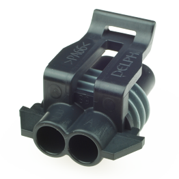
At this type of connection a male connector is linked with a female connectors and “filled” with terminals on both sides. As a result you will have a linkable part of a harness. Mainly this kind of connection is used to connect or disconnect any small application (e.g. electrical window lift) with the main power harness or any other kind of partial harness. A very common wire-to-wire connection system is Metri-Pack 280.Synonym: Wire-to-wire Connector, Inline Connector
Board-to-wire Connection
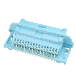
This kind of connection system is used to fix a connection onto a conductor board. Mainly the male connector named “PCB Header” is fixed with the conductor board. The female connector is linked to the male connector so the female terminals are connected to the wiring harness. A very typical Board-to-Wire connection is to connect the engine control unit with the power harness. A good example is Micro-Pack 100W Header Unsealed Series.Synonym: Board-to-wire Connector, PCB-Header
Device Connections
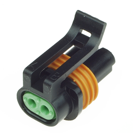
Here we have the mating part already assembled within a device. Mating parts on devices are mainly the female connectors matching to the given application. In most cases the assembled male connectors are not available for sale. Very annoying for most developers who want to build up connection systems for testing purposes. Example given for a common Device Connections can be found in sensor applications as the Metri-Pack 150.2 Pull-to-Seat Series.The Components of Connection Systems and their functionality
In the following you will find the general elements of connection systems, their wordings and functions in any connection system. Your hints and personal input would be much appreciated in keeping this Wiki alive.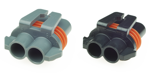
Connector housing
The connector housing is used to carry the pins/terminals. It is made of insulating plastic and its shape secures the connection with the given mating part. The design differentiates between male and female connectors as well as sealed and/or unsealed connection systems. In a sealed connection system you will generally find a radial sealing to protect the electrical system from water or dirt influence. This is located between the male and female connector [2].To avoid misconnections many connectors are produced in different codings. The coding of a connector is often realised by a variety of notches inside the connector. As these notches are not visible at first sight, these coded connectors manufactured by Delphi Connection Systems are mostly marked with different colours so these are easy to use even for people new to the business. The connectors shown in the pictures above are good examples of connectors with different coding. (Picture left 12059181, right 12059183)
Synonym: connector, connector housing
Secondary Lock / Terminal Position Assurance (TPA)
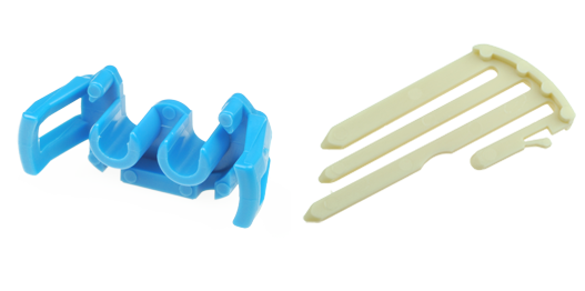
Terminals are mainly assembled by hand into the connector housing. To do this each crimped contact must be inserted fully into the connector to insure a completed technical link. The insertion force varies from the different connection systems and its use. On many connection systems you will here a slight „click“ as soon as the terminal is pluged in. This slight click sound is established to avoid mistakes in mass production. You can imagine that if any worker is assembling terminals 8 hours a day mistakes might happen and these need to be reduced as best as possible. If you consider that a worker can make a maximum error of one mistake in three months he has a mistake rate of less than 10 ppm (ppm = parts per million) [2].Furthermore securing a perfectly assembled terminal with given connector Secondary Locks are used. Secondary Locks are produced and available for nearly all connectors differing in shape of terminals and shape of each connector housing. The use of a secondary lock insures the terminals are fixed perfectly in its end position. Some secondary locks fulfil the function of strain relief [2]. The pictures besides shows two different kinds of Secondary Locks.
(Picture left 12059185, right 12010852)
Synonym: Secondary Lock, TPA, Strain Relief
Connector Position Assurance (CPA)
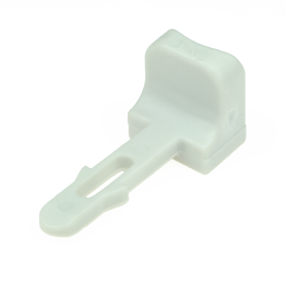
Each connector is assembled with its mating part to a connection system by hand. The required mating force differs from the amount of cavities, terminal and connectors shape. If the connectors are not fully assembled you might have an electrical connection, however it's not protected from water, dirt or vibration influence and might lead to a malfunction of the connection system. To secure the correctly assembled connection system a Connection Postion Assurances (CPA) is used. Connection Position Assurances are available in many different shapes, as preassembled parts and many more – always depending on each connection system and their technical use. Nevertheless the Connector Position Assurance will always indicate to the user through a slight click sound that the connection is assembled perfectly. (Picture left 12020833)Synonym: Connector Position Assurance, CPA
Single Wire Seal
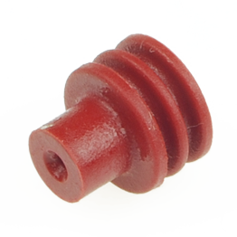
Single Wire Seals surround the single conductor and seal the cavity against environmental conditions. Seals are crimped to the terminal and to the cable in one working step and than pushed into each cavity. Due to manufacturer and series a seal varies from 2 to 3 sealing disks which are forced from the inside against the cavity. Depending on the manufacturer and series the single wire seals are retained with different percentages of silicon oil. The use of this oil supports the assembly process while inserting into a cavity.(Picture left Delphi 12015899)
Synonyme: ELSeal, Single Wire Seal
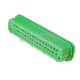
Blockseal
Blockseals have the same functions like single wire seals. They also protect the cavity against outdoor influences. As a main difference a block seal offers several openings to retain several cables in each opening. Therefore a blockseal protects several cavities. Blockseals are not crimped to any terminal as they are already assembled to the connectors body(Picture left Delphi 12110489)
Synonyme: Blockseal, Multiple Cable Seal
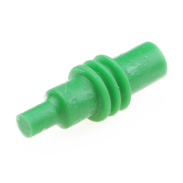
Cavity Plug
Cavity Plugs are used to block unused cavities and protect these against environmental conditions. Inserting a cavity plug can be done by hand. The top edge of the cavity plug should be pushed in a minimum of 2 mm into each cavity. To remove the cavity plug you can use a screwdriver.The following picture reflects a standard cavity plug as an example.
(Picture left Delphi 12010300)
Synonyme: Cavity Plug, Plug
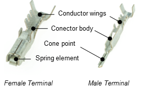
Design of Terminal Systems
Terminals are differentiated by gender into „male“ and „female“ terminals. Female terminals are manufactured with one or several spring elements which show a bell-mouthed opening. This aperture makes it easy to find and insert the male terminal. The male terminal is slightly thinned at its cone point and can be fixed easily to the female terminal spring elements. The zone for inserted male and female terminals are called contact zones. While assembling male and female terminals the male terminal is slightly elastically deformed in order to reach the desired electrical pressing force. The pressing force is a basic factor while working with terminals and connection systems. Terminals ends are named „conductor wings“. These wings are used to crimp the terminal to the cable [1]. (Picture left 12103881, right 12045773)Synonyms: Terminal, Single terminal, male terminal, female terminal
Performance indicators of Terminals
Contact resistance
Contact resistance is a sum of the following single resistor factors:- Ferule Resistor: depends on the used method of assembling terminals (e.g. crimping, soldering etc) and its assembling quality. To reduce ferule resistor to the lowest possible level it is highly recommended to use the correct cable and correct cable diameter on each terminal. It is also highly recommended to use the professional crimping tools available on each terminal. In general the terminal producing companies do offer crimping specifications for each terminal to insure terminals are used effectively. Crimp specifications can be requested at DeyTrade.
- Resistor force of male and female terminals: Short overall length, big cable diameters and used material with high conductance secures best possible value of resistance.
- Contact resistance at contact zone: Contact resistance at contact zone is a result of constriction resistance and surface contamination resistance. The constriction resistance lowers by raising the contact surface, raising terminal normal force and raising electrical conductance. Depending on the terminals surface coating a thin corrosion coat can be found inside the terminal connection. The corrosion coat has its own resistance differing from used terminal systems. While assembling or disassembling the terminals the corrosion coat can be destroyed [1].
Continuous current-carrying capacity
Continuous current-carrying capacity is one of the main characteristics. Continuous current-carrying capacity is given in Ampere [A] and is limited by heating as a result of the current flow. Responsible for the heating process of terminals is the terminal resistor [1].Plug- and Pull-Force
The used plug and pull force is mainly influenced by the sum of mating force of each terminal system. The friction between the connector housings is insignificant. The more cavities inside a connection system that are used the lower plug and pull forces are needed to secure terminals from damage and to make plug-in easy. Plug and pull force is influenced by form and shape of each terminal, surface roughness and hardness of given terminals. [1].Material for Terminals
Basic material: The basic material of any terminal needs to have a very high electrical and thermal conductance to reduce heating at its best and to insure best possible current carrying capacity. For these reasons the favourable material used is copper and its alloys. The requirements in the automotive industry for terminals material and a trend to miniaturisation led to a change in material use. Copper-Zinc (e.g. CuZn30) and Copper-Bronze (e.g. CuSn4) are slowly beeing replaced by Copper-Nickel-Silicium (CuNiSi) alloys.CuNiSi alloys are showing better results regarding resistance and conductibility. As a result you will be able to have terminal systems with higher ampacity and higher limit temperature [1].
Terminal Plating: To avoid corrosion basic materials of terminals are galvanized. Common terminal platings are gold, silver and tin.
Gold Plated Terminalsare used at:
- extreme electrical conditions: very small allowance of changes in contact resistance, submitting signals at small voltage levels and high data rates.
- extreme environmental conditions: very high pollutant concentration and temperatures above 150°C, high vibration surroundings, high rate of assemble and disassembling over lifetime.
- extreme reliability: long lifetime, low error probability.
- Terminal systems with low terminal normal forces
Silver Plated Terminalsare used
- at High Voltage Systems,
- if value of assemble and disassembling terminal/connection systems is 20-50 over lifetime
- to avoid fretting corrosion
- if surrounding temperature does not exceed 140°C-160°C
Tin Plated Terminalsare the most common used terminals and are mainly used
- if value of assemble and disassembling terminal/connection systems is 10-20 over lifetime
- if surrounding temperature will not excess 130°C-150°C [1].
[1] Volker Behrens: Elektrische Kontakte – Werkstoffe, Gestaltungen und Anwendungen in der Nachrichten-, Automobil- und Energietechnik. expert Verlag, Renningen 2010, S.106 f.
[2] Günter Knoblauch: Steckverbinder – Systemkonzepte und Technologien. expert Verlag, Renningen 2002, S.211


Der Versand ist promt und die Seite übersichtlich. Danke